- CYPE >
- english >
- products >
- CYPECAD MEP >
- Numerical analysis of linear thermal bridges


CYPE Ingenieros has collaborated with the Miguel Hernández University of Elche (Alicante) to carry out an investigation project to develop a software tool to integrate the numerical analysis of thermal bridges for the energy demand calculation of buildings. The project has been financed by the “Centro para el Desarrollo Tecnológico Industrial (CDTI)” and co-financed by the “European Regional Development Fund (ERDF)”. The result of this project is a software tool, which based on the geometry of a building, identifies and analyses the thermal bridges included in its thermal envelope.
This project has been captured in the Numerical analysis of linear thermal bridges module, which carries out a precise analysis of the Linear transmittance of the thermal bridges CYPECAD MEP exports to EnergyPlus™ from the Air conditioning tab.
- Investigation project
- Operation of the Numerical analysis of linear thermal bridges module
- Activation of the linear thermal bridge analysis
- Analysis
- Ventilated façade management
- Results
- Linear thermal bridges analysed by the module
- User license requirements
- How the thermal bridges are used by CYPECAD MEP
Investigation project
The Miguel Hernández University and CYPE Ingenieros have carried out an investigation project to develop a software tool to integrate the numerical analysis of thermal bridges when calculating the energy demand of buildings. The project has been financed by the “Centro para el Desarrollo Tecnológico Industrial (CDTI)” and co-financed by the “European Regional Development Fund (ERDF)”. The result of this project is a software tool (the Numerical analysis of linear thermal bridges module of CYPECAD MEP), which calculates the thermal bridges in the thermal envelope of buildings using a finite element numerical analysis.
For this investigation project, CYPE Ingenieros have collaborated with the “Grupo de Ingeniería Energética” of the “Departamento de Ingeniería de Sistemas Industriales” of the Miguel Hernández University, whose investigators have participated in the initial definition of the project, the modelling of the thermal bridges and in the validation of the final results of the program.
Thermal bridges are zones of the building envelope at which there is a difference in the uniformity of the construction assembly (change in thickness of the façade, materials used, penetration of the construction elements with different conductivity, etc.). Their thermal resistance is less than that of the other façades and cause heat loss in the building.
The heat loss via the thermal bridges considerably affects the energy demand results, and can represent, in some cases, up to 40% of the thermal losses of the building. Therefore, it is essential the properties of the thermal bridges be taken into account to carry out a precise analysis of the energy requirements of the building. This is possible with the Numerical analysis of linear thermal bridges module of CYPECAD MEP.
Operation of the Numerical analysis of linear thermal bridges module
Activation of the linear thermal bridge analysis
Once the construction elements have been introduced in CYPECAD MEP, the thermal bridges of the thermal envelope of the building are identified immediately by the program when the analysis is launched (Results > Analyse) in the Air conditioning tab of the program. During the same analysis process, the Numerical analysis of linear thermal bridges module analyses the thermal bridges that have been detected if users have activated the Numerical analysis of linear thermal bridges option in the General data dialogue box (Job > General data).
Analysis
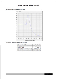
The Numerical analysis of linear thermal bridges carries out the analysis of thermal bridges using a finite element analysis based on the two-dimensional heat transfer analysis reflected in the EN ISO 10211 code. Using this computer simulation technique, the Thermal transmittance of each thermal bridge is obtained.
This way, a more exact analysis is obtained of the real behaviour of the thermal bridges, since not only the position of the insulation in the construction elements is taken into account, but also the materials it is composed of.
Ventilated façade management
Ventilated façades contain a ventilation chamber between the outer finish and the insulation layer. These construction solutions are seen more and more every day to limit the energy demand of buildings; the layer of heated air generates a current of continuous ventilation in the façade.
The Numerical analysis of linear thermal bridges module analyses these construction elements in the same way as when their thermal transmittance is analysed. Therefore, when the thermal bridges of the ventilated façades are analysed, the total thermal resistance of the façade is obtained by ignoring the resistance of the air chamber and the remaining layers that lie between it and the outside, including an exterior surface resistance corresponding to calm air, equal to the interior of the same element. The temperature of the air chamber is considered to be the same as the temperature outside.
Results
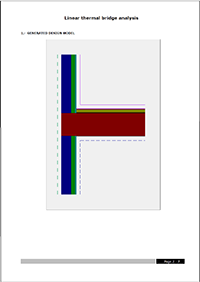
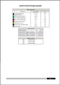
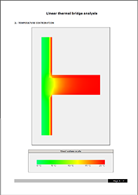
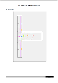
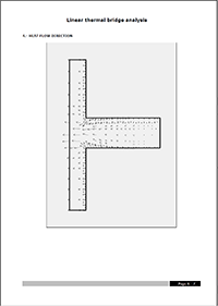
After the analysis, using the Thermal bridge view option in the Results menu, the program displays the type of thermal bridges that have been detected and their transmittance (displayed on-screen next to the construction elements). By clicking on the edges, more information can be obtained on the analysis of the thermal bridge: model used in the finite element analysis (including the materials, thermal conductivity, surrounding conditions, etc.), temperature distribution in the thermal bridge, heat flow lines, etc.
Linear thermal bridges analysed by the module
The Numerical analysis of linear thermal bridges currently analyses the seven thermal bridges most commonly found in a building:
 |
 |
") |
") |
 |
 |
 |
More thermal bridge types will be implemented in upcoming versions.
User license requirements
For CYPECAD MEP to be able to automatically analyse the thermal bridges included in the building envelope, the user license must contain the permits to use the following modules:
- Numerical analysis of linear thermal bridges
- Export to EnergyPlus™ (if users wish to export data to this program or use it as the analysis motor).
How the thermal bridges are used by CYPECAD MEP
The thermal bridges of the building, defined by users or analysed using the Numerical analysis of linear thermal bridges module, are used in CYPECAD MEP for the following processes:
- Intervene when calculating the heating thermal loads.
If users select the UNE code to calculate the heating thermal loads, the program takes into account the thermal losses due to heat transmission to the outside and to non-heated spaces, which are produces via the linear thermal bridges identified by the program. - Export to EnergyPlus™, internationally recognised software for the thermal and energy simulation of buildings, developed by the DOE (Derpartment of Energy, United States) with which the energy demand and consumption analyses can be carried out.
- Use of EnergyPlus™ as an analysis motor to obtain the thermal demand of a building and compare it with that of the reference building.